Would be great to know if it worked. 
1 Like
sorry unfortunately I had reached my “13 replies max on first day” or something so have been unable to respond until now
unfortunately it didn’t work, it says the #include <button.h> doesn’t exist lol
That’s a common problem caused by copying the code from the site rather than using the button to download the ZIP file that has all the additional required files. Once you’ve got the ZIP, extract all the files to the folder where your current .ino file is and that should resolve it.
I’ve downloaded the required files and opened the code in Arduino IDE to check that it compiles and I had to fix two things so here’s the complete code that at least compiles:
#include <SPI.h>
#include "Button.h"

#define PUSHBUTTON_PIN_7 7
#define PUSHBUTTON_PIN_8 8

int CS_signal = 2; // Chip Select signal onsul pin 2 of Arduino
int CLK_signal = 4; // Clock signal on pin 4 of Arduino
int MOSI_signal = 5; // MOSI signal on pin 5 of Arduino
byte cmd_byte2 = B00010001 ; // Command byte
int Ri = 100; // Setting up the initial value

Button btnRup(PUSHBUTTON_PIN_8); // pin 8 (red button) will increase resistance
Button btnRdn(PUSHBUTTON_PIN_7); // pin 7 (blue button) will decrease resistance

void setup() {
    pinMode (CS_signal, OUTPUT);
    pinMode (CLK_signal, OUTPUT);
    pinMode (MOSI_signal, OUTPUT);

    btnRup.init();
    btnRdn.init();
    initialize();

    Serial.begin(9600);                                                     // setting the serial speed
    Serial.println("ready!");
}

void initialize() {
        // send the command byte of value 100 (initial value)
    spi_out(CS_signal, cmd_byte2, Ri);
}

void spi_out(int CS, byte cmd_byte, byte data_byte){ // we need this function to send command byte and data byte to the chip
    digitalWrite (CS, LOW);                                                 // to start the transmission, the chip select must be low
    spi_transfer(cmd_byte); // invio il COMMAND BYTE
    delay(2);
    spi_transfer(data_byte); // invio il DATA BYTE
    delay(2);
    digitalWrite(CS, HIGH);                                                 // to stop the transmission, the chip select must be high
}

void spi_transfer(byte working) {
    for(int i = 1; i <= 8; i++) { // Set up a loop of 8 iterations (8 bits in a byte)
        if (working > 127) {
            digitalWrite (MOSI_signal,HIGH) ; // If the MSB is a 1 then set MOSI high
        } else {
            digitalWrite (MOSI_signal, LOW) ;
        } // If the MSB is a 0 then set MOSI low

        digitalWrite (CLK_signal,HIGH) ;                                        // Pulse the CLK_signal high
        working = working << 1 ;                                                // Bit-shift the working byte
        digitalWrite(CLK_signal,LOW) ;                                          // Pulse the CLK_signal low
    }
}


void loop() {
    bool Rup = btnRup.read();
    bool Rdn = btnRdn.read();

    if (Rup) {
        Ri += 10;
    }

    if (Rdn) {
        Ri -= 10;
    }

    if (Ri > 255) {
        Ri = Ri - 255;
    }

    if (Ri < 255) {
        Ri = Ri + 255;
    }

    spi_out(CS_signal, cmd_byte2, Ri);

    if (Rup || Rdn) {
        delay(500);
    }
}
1 Like
apparantly “button” does not name a type…for button 7… after 3 other times “button” has been mentioned/
sorry i seem to be having issues as i got the same error message for trying to respond earlier, apparantly i’m talking too much so I’m gonna try and put all problems and questions in 1 post incase i cant respond for a few hours again.
- where do i find these files? am i likey to need more? what was the clue i missed that would have implied i need to do that?
2)does the command byte always have to be B00010001 ? why B17? does it not matter?
-
“#define PUSHBUTTON_PIN_7 7” does it have to be written like that? i didnt find that in the library. am i looking in the wrong place?
-
am i right in guessing that one of the changes was that there were multiple setup loops? i vaguely remember something about only being able to have 1 setup loop, if there is a limit on the number of set up loops, is there a limit to how big the setup loop can be?
-
What’s “working”, why does it get bithsifted?
-
how do you troubleshoot? is it just from aquired knowledge or do you maybe also use resources i havent found that can translate what the code says into what the code means? or the error messages etc?
-
what would you say is the most efficient way for me to get better at programming arduino? is it really just a case of “read the examples and guess” or are there like actual tutorials available to give you a better understanding of arduino and programming?
thanks man!
1 Like
also, how come neither the digipot control code nor the LED button example codes require the #include <SPI.h> or the #include “button.h”?
Sorry for the delay, I went for a walk along the sea front after dinner with my family.
I can see how that might be confusing. The first mention of button in the #include "Button.h" tells the compiler to include the contents of the file named Button.h which is a header file that defines the things available in Button.cpp. You include this file so that you can define a Button class and invoke methods like read() on instances of the button.
The #define PUSHBUTTON_PIN_7 7 tells the compiler to define a label called PUSHBUTTON_PIN_7 and assign it the value 7. I would personally have named it something like RUP_BTN_PIN so that the pin number could change without changing the label. It’s common to given constants all caps names to make it clear that they can’t be changed in the code later.
The Button btnRup(PUSHBUTTON_PIN_7) line declares an instance of a Button class and names it btnRup.
So yeah, lots of mentions of “button” eh.
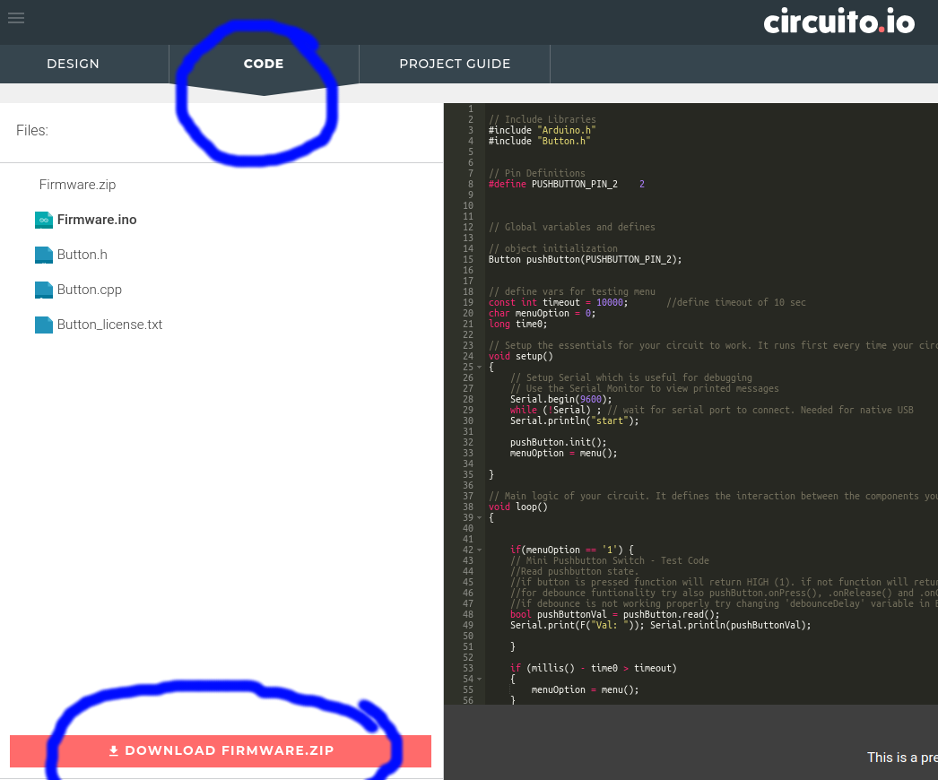
You get the files from the Code tab of Circuito if you download the ZIP file. Here’s a screenshot:
This I don’t know. I assumed this was something to do with the digital potentiometer code you have.
As I mentioned above, it’s not the style I’d use. I might even have been lazy enough to skip the define statements and just specified the pin number in the button declaration like this:
Button btnRup(8);
Button btnRdn(7);
The parameter working is passed to the method to do the SPI communications. If you want to read more about bit shifting, this is a good Stack Overflow answer: https://stackoverflow.com/a/141873/39722
It’s a mixture of both. With experience you acquire knowledge of what things mean and you know (or assume) to work. You then focus on what you don’t know for certain. An approach that has worked well for me is to reduce complexity and remove “links” in the “chain”. So in this case I’d comment the code related to the potentiometer (“pot”) and just serial print the Ri value whenever a button is pressed. That way you can determine that the buttons are working. Then you move onto the next thing - controlling the pot. Even the biggest systems are made up of small programs.
There are a lot of different learning styles. You may know what works for you, or you may need to find out. Some people like to learn from books, others prefer a real life tutor who they can ask questions of, and others prefer videos or online courses. I’ve watched probably over 100 hours of YouTube videos to learn more about Arduino (and other controllers like the MSP430, ESP8266, ESP32) and I guess it helps that I’ve been programming since 1984 - you know, when we all had dinosaurs as pets. 
SPI is a communication protocol. I assume the digipot needs it. You could comment the line and see what fails - one way to see for certain what needs it. hehe
Good luck and don’t give up. I know it can be frustrating at times, but the joy of getting your creation to [finally] work is priceless. 
1 Like
Oops, I just noticed I didn’t answer your question about the setup and loop functions. You can only have one of each, but their size is only limited by the memory available in the Arduino.
1 Like
dude this is amazing. honestly man, thank you so much for taking the time to help a random dum-dum online like this!
I’m gonna get to work on this now, will let you know how i get on.
1 Like
oh god.
you’re going to need to brace yourself. You may need to brace yourself for the magnitude of stupid that’s about to hit you.
i downloaded the files and must have put them in the wrong place… could that be why i keep getting an error message like :
Preformatted textInvalid library found in C:\Users\louis\Documents\Arduino\libraries\Firmware: no headers files (.h) found in C:\Users\louis\Documents\Arduino\libraries\Firmware
Invalid library found in C:\Users\louis\Documents\Arduino\libraries\MCP41010DPcontroll: no headers files (.h) found in C:\Users\louis\Documents\Arduino\libraries\MCP41010DPcontroll Preformatted text
i have no idea what a .ino file is…
i tried searching for it in the search part of windows explorer but it just came up with such a huge list of things i got lost. most of the were arduino related.
i seem to have one arduino folder in one directory like “downloads” and then another part in some hard to find programs(x86) folder that i cannot find by just navigating throught the menus. apparently “users” was in the file path but i couldnt find it when i tried doing it myself.
should i perhaps just uninstall and re-install everything?
thanks again
The .ino file extension is used by the Arduino editor, also known as the Arduino IDE.
1 Like
It’s kind of working now, although the DigiPot seems to be cycling through it’s resistance ladder with or without button presses.
I’ve tried playing with the resistance increments in the loop and the delay and it doesn seem to make a difference… but then again now that I’ve been observing it for a while, the LED is getting dim/bright at an eratic pace.
could it be :
`void spi_transfer(byte working) {
for(int i = 1; i <= 8; i++) { // Set up a loop of 8 iterations (8 bits in a byte)
if (working > 127) {
digitalWrite (MOSI_signal,HIGH) ; // If the MSB is a 1 then set MOSI high
} else {
digitalWrite (MOSI_signal, LOW) ;
} // If the MSB is a 0 then set MOSI low
    digitalWrite (CLK_signal,HIGH) ;                                        // Pulse the CLK_signal high
    working = working << 1 ;                                                // Bit-shift the working byte
    digitalWrite(CLK_signal,LOW) ;                                          // Pulse the CLK_signal low
}
}
`
is maybe telling the digipot just to loop its’ cycle regardless?
thanks
My guess, not knowing this device but knowing done others, is that the communion interface requires sending one bit at a time. That’ll explain the 8 in the for loop, and the bit shifting.
If I may, I’d suggest commenting or removing this line in your loop:
spi_out(CS_signal, cmd_byte2, Ri);
And add a line to print the value to the serial interface. That way you can test the logic and buttons without the complexity of the digipot:
Serial.println(Ri);
Come to think of it, the update of the digipot (and now the serial print line) should be inside the block of code that only runs if a button was pressed:
if (Rup || Rdn) {
    Serial.println(Ri);
    //     spi_out(CS_signal, cmd_byte2, Ri);
    delay(500);
}
Then if you open the serial monitor in the Arduino IDE you’ll see the value printed whenever you press a button.
1 Like
thanks man I’ll get to that in a mo…there may be earth fault somewhere in the circuit as unplugging the 5Vsupply to the breadboard keeps the LED lit and still changing brightnesses lol It’s like its getting supply from ground, like there’s a loop…
OK so i’ve tried your latest suggestions and now, the error message i get is " ‘class HardwareSerial’ has no member name ‘printIn’ "
also, when i opened the serial monitor, literally nothing happened when i pushed buttons, it just said “ready”.
I’ve tried making a direct connection between those 2 same buttons to an LED and a 1kOhm resistor to test the buttons themselves and they do work. So i’m now a little lost again i’m afraid.
OK so, i finally realised that instead of print IN it’s printLn but now the LED doesn’t change state at all lol
Serial Monitor does show the numbers change from 0-255 upon pushing buttons however it seems to want to defualt to 255
I’m so sorry I’ve been busy all day, then immediately after work I was preparing a kitchen worktop for my daughter’s house and after that I was finishing a D&D game box for my son. I’ve just finished and it’s 10pm. I’m up at 6 tomorrow to go fit the kitchen worktop. No time!
But doesn’t it look good! 
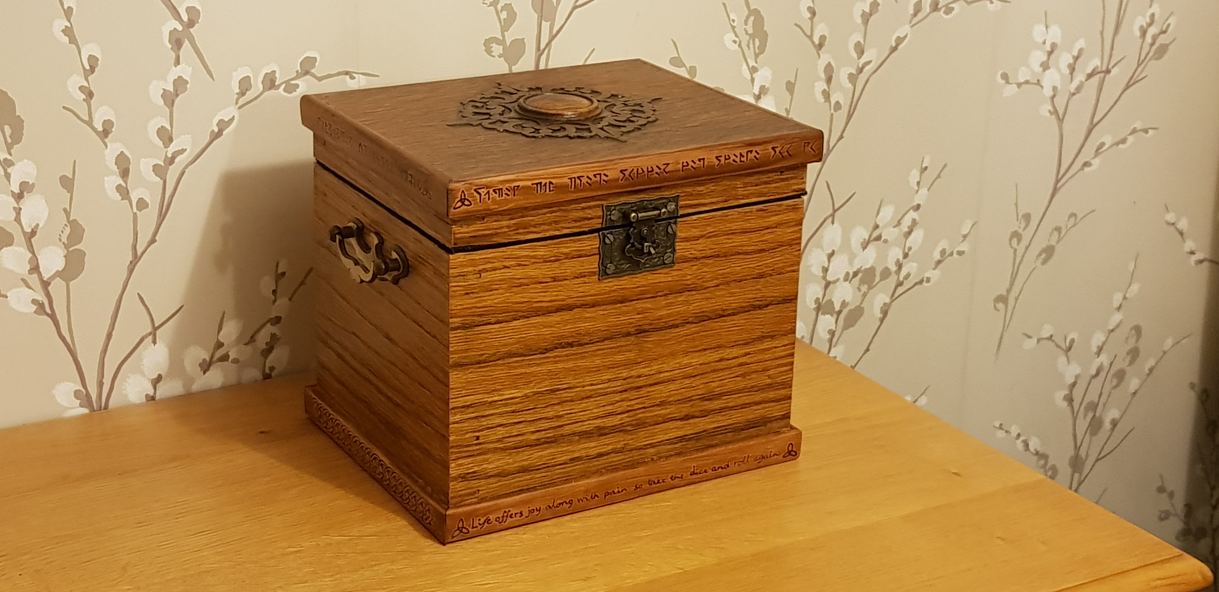
Not a problem man it looks good! i just got into D&D myself about 6 months ago but sadly have not really had a chance to play for a while lol
not a problem mate, enjoy the handyman adventures!
Here’s the modified loop (and entire code to avoid confusion) that should let you see the value of Ri in the serial monitor as well as whether the up or down button was pressed. I’ve also commented the call to update the digipot (so expect that to do nothing) and added a 10ms delay to avoid the loop “running hot” (it really doesn’t need to run at full speed for human input).
With these changes you should be able to verify that the buttons and the Ri value are behaving as expected. Once you’ve confirmed that, you can start looking at the next part of the system - the digipot.
#include <SPI.h>
#include "Button.h"

#define PUSHBUTTON_PIN_7 7
#define PUSHBUTTON_PIN_8 8

int CS_signal = 2; // Chip Select signal onsul pin 2 of Arduino
int CLK_signal = 4; // Clock signal on pin 4 of Arduino
int MOSI_signal = 5; // MOSI signal on pin 5 of Arduino
byte cmd_byte2 = B00010001 ; // Command byte
int Ri = 100; // Setting up the initial value

Button btnRup(PUSHBUTTON_PIN_8); // pin 8 (red button) will increase resistance
Button btnRdn(PUSHBUTTON_PIN_7); // pin 7 (blue button) will decrease resistance

void setup() {
    pinMode (CS_signal, OUTPUT);
    pinMode (CLK_signal, OUTPUT);
    pinMode (MOSI_signal, OUTPUT);

    btnRup.init();
    btnRdn.init();
    initialize();

    Serial.begin(9600);                                                     // setting the serial speed
    Serial.println("ready!");
}

void initialize() {
        // send the command byte of value 100 (initial value)
    spi_out(CS_signal, cmd_byte2, Ri);
}

void spi_out(int CS, byte cmd_byte, byte data_byte){ // we need this function to send command byte and data byte to the chip
    digitalWrite (CS, LOW);                                                 // to start the transmission, the chip select must be low
    spi_transfer(cmd_byte); // invio il COMMAND BYTE
    delay(2);
    spi_transfer(data_byte); // invio il DATA BYTE
    delay(2);
    digitalWrite(CS, HIGH);                                                 // to stop the transmission, the chip select must be high
}

void spi_transfer(byte working) {
    for(int i = 1; i <= 8; i++) { // Set up a loop of 8 iterations (8 bits in a byte)
        if (working > 127) {
            digitalWrite (MOSI_signal,HIGH) ; // If the MSB is a 1 then set MOSI high
        } else {
            digitalWrite (MOSI_signal, LOW) ;
        } // If the MSB is a 0 then set MOSI low

        digitalWrite (CLK_signal,HIGH) ;                                        // Pulse the CLK_signal high
        working = working << 1 ;                                                // Bit-shift the working byte
        digitalWrite(CLK_signal,LOW) ;                                          // Pulse the CLK_signal low
    }
}


void loop() {
    bool Rup = btnRup.read();
    bool Rdn = btnRdn.read();

    if (Rup) {
        Serial.print("UP ");
        Ri += 10;
    }

    if (Rdn) {
        Serial.print("DN ");
        Ri -= 10;
    }

    if (Ri > 255) {
        Ri = Ri - 255;
    }

    if (Ri < 255) {
        Ri = Ri + 255;
    }

    if (Rup || Rdn) {
        Serial.println(Ri);
        //spi_out(CS_signal, cmd_byte2, Ri);
        delay(500);
    }

    delay(10);
}
1 Like
thank you so much this is amazing man! unfortunately i found an alternate version that directly applies to the bluetooth function i was hoping to add to it. I had first thought that getting it to work with buttons would make it easy to just add the bluetooth function.
If you’re interested, it’s found here:
thanks for all your help man!
1 Like