I am a student and I am trying to follow the wiring in https://www.circuito.io/app?components=9443,200000,842876 but for some reason it is not working at all. the code that I am using is bellow. thanks to anyone that can help
import RPi.GPIO as gpio
import time

GPIO_PIN = 4
gpio.setmode(gpio.BCM)
gpio.setup(GPIO_PIN, gpio.OUT)

try:
   while True:
      gpio.output(GPIO_PIN, gpio.HIGH)
      passcode = raw_input("What is pi? ")
      if passcode == "A":
         for x in range(20):
            gpio.output(GPIO_PIN, gpio.LOW)
            time.sleep(1)
            gpio.output(GPIO_PIN, gpio.HIGH)
            time.sleep(1)
      else:
         gpio.output(GPIO_PIN, gpio.HIGH)
         print("Wrong")

except Exception as e:
   print('Exception message: ' + str(e))

except KeyboardInterrupt:
   print('\nProcess interrupted...')

finally:
   gpio.cleanup()
1 Like
A good approach when nothing is working is to simplify things until it works, or start from the basics and add complexity until you find what doesn’t work.
I’d suggest connecting an LED and resistor between PIN 4 and ground and then test the code. If the LED blinks then the code is working. If not, the LED might be the wrong way around, so swap the LED wires around. Your circuit is then simply the Pi, the power supply, and the LED (with resistor).
Good luck! 
Well tried that and no luck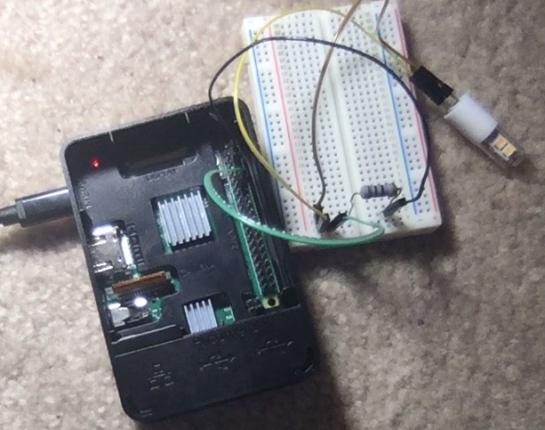 Hopefully the picture shows the setup. I know the LED works because I just tested it by touching the terminals of a battery. the resistor is a 100 Ω 1W (cannot find a 250mW to safe my life).
I’m not that familiar with the Pi. It’s quite easy to get confused about which pin is which on some boards. Can you change the program to set the pin high and leave it high?
With that done, you could leave the wire going to ground and move the other one from one pin to the next to see if maybe you’re connected to the wrong pin.
Could you share your code for us to see?
Afterthought: LEDs only allow current to flow in one direction. Have you tried swapping the LED leads to see if it’s “backwards” in the circuit?
PPS. I see Pi has different PIN references so there’s a very real chance you are connected to the wrong pin. See this good explanation of PINs on the Pi: https://raspberrypi.stackexchange.com/a/12967
Code is in original message, but the modified code to do what you just suggested is:
import RPi.GPIO as gpio

GPIO_PIN = 18
gpio.setmode(gpio.BCM)
gpio.setup(GPIO_PIN, gpio.OUT)
gpio.output(GPIO_PIN, gpio.HIGH)
I went as far as changing the code to do a loop through all of the available GPIO pins# and see which one light up the bulb and none worked. After I cycled through all of the pins I swapped the LED cables to make sure that was not the problem and repeated the process. Again no luck. I am beyond stumped at this point.
Do you have a multimeter or oscilloscope? With one of these you could test the voltage difference between ground and each pin whilst the program is running.
Is this your very first project, or have you had success with the IO pins of this Pi in other projects?
Don’t give up, these difficulties will make success all the more rewarding when you get there.
What model of Pi do you have Jose?
Have a multimeter, connected it to the pins I am getting 3v. Is this my first project, yes. I am about to make a hole the size of my on the wall.
Raspberry 3 B+ (I guess I need to add additional stuff to make the massage over 20 characters long, that should suffice)
I know right - it can be SO infuriating when we struggle to get even the simplest thing to work!
But it sounds like you’ve managed to verify that the pin is the correct one and you are controlling it. Could you edit your loop to repeatedly set the pin HIGH, wait for a second, and then set it LOW and wait for a second? If you connect the multimeter again, please let us know if the voltage goes up, then drops to zero, then goes up, etc.
This will confirm for certain that the PIN output is working as your code intends. The next thing after that is to assess the wiring to see if you have poor connections or broken wires. (You could test the jumper leads with the multimeter as well.) Test the LED using two 1.5V batteries to see which (negative) wire should go to ground and the other to the IO pin.
When you analyse each link in the chain in enough detail, you will find the cause of the issue. Just don’t give up and if you’re getting angry, take a break until you can calmly analyse the issues again.
(If only I could take my own advice!  )
)
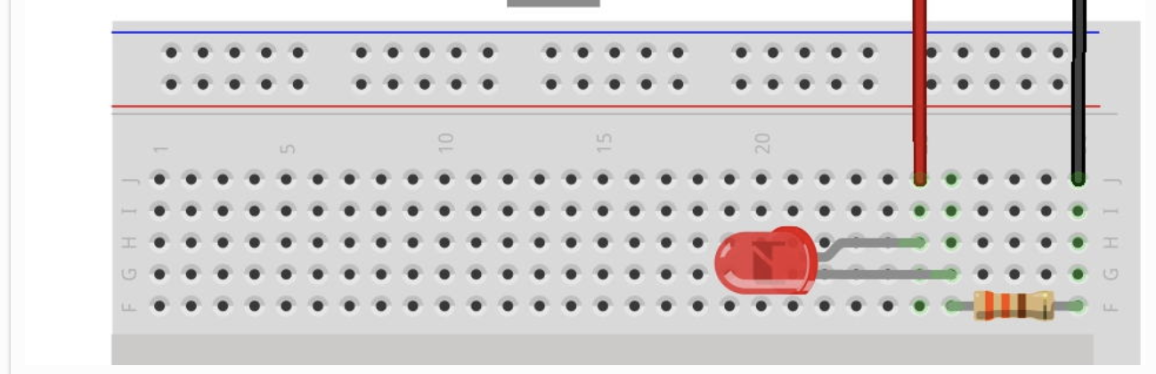
OK got an LED to work. Using this diagram
and the code used is
import RPi.GPIO as gpio
import time

x = 18
gpio.setmode(gpio.BCM)
gpio.setup(x, gpio.OUT)

try:
   while True:
      gpio.output(x, 0)
      time.sleep(2)
      gpio.output(x, 1)
      time.sleep(2)

except Exception as e:
   print('Exception message: ' + str(e))

except KeyboardInterrupt:
   print('\nProcess interrupted...')

finally:
   gpio.cleanup()
My previous problem with the LED is that the one I was using was a 12V LED so I scarified one of my mom’s led tea lights in the name of science. Now it works.
Not yet, wanted to go to bed after a small win. The solenoid is 12V so the output from the Pi should not be enough to power it up so I will need to get the external power supply inserted into the the circuit. the diagram tells me to do it one way, but that is obviously not working, so i don’t have the first clue on how I would do it.
Disclaimer: I’m not a professional electronics engineer and I’m very much on the learning curve as well. Hopefully the little I know is enough to help you get what you want done.
I see the circuito project in your original message uses a MOSFET. MOSFETs let us (amongst other things) control a higher voltage (12V in this case) from the lower voltage of our controllers (Arduino, Pi, etc.). I find it easiest to think of the MOSFET as a tap that you open with 3.3/5V and allow the 12V to flow through.
If you don’t have the exact same MOSFET, check which pins are the Gate, Source, and Drain; they’re not always in the same order. There’s a good video on MOSFETs by AddOhms here: https://www.youtube.com/watch?v=GrvvkYTW_0k
He also produced a useful PDF guide here: http://addohms.com/mosfet-guide
Finally, be careful when connecting it all up; the diode must go the right way around. Diodes only allow current to flow in one direction - another opportunity for one of those “nothing works” moments.
I tried to open the project guide but for some reason it seems disabled. Here: https://www.circuito.io/static/reply/index.html?solutionId=5c7ebde26e58290030754278&solutionPath=storage.circuito.io
So I swapped the board out for a Node MCU and the project guide works. If you ignore the fact that the controller is different, the wiring is the same so you can follow the instructions in a friendly step-by-step guide (click the “Wire” link on the left): https://www.circuito.io/static/reply/index.html?solutionId=5c7ecf381708700030f8f004&solutionPath=storage.circuito.io
I used the following datasheet to figure the pins, since it is the one that I purchased. https://datasheet.octopart.com/FQP30N06-Fairchild-datasheet-21999.pdf
I’ll have to look at that video when I get home. I was also looking for the wiring step-by-step and couldn’t get it to work, so I moved on from there, but I’ll look at the one you pointed at.
1 Like